

Hello, INNOvators!
Get ready to uncover the latest innovation in the LXR project—one that could change keyboard design as we know it. Today, we're exploring how to create a diode-less keyboard matrix that not only simplifies our design but also effectively limits ghosting.
👻 Ghosting in Keyboard Matrix
Ghosting occurs when multiple keys are pressed simultaneously, and the keyboard mistakenly registers additional, unintended key presses. This issue often arises in standard keyboard matrices when three corners of a rectangle are pressed simultaneously, causing the fourth corner to appear as a 👻
The most common solution to this problem is to use diodes ensure the current flow only in one direction eliminating ghosting… but we don’t want that…
Given that the cause of ghosting is pressing 3 corners of a rectangle, another solution is to virtually eliminate rectangles.
Why Go Diode-less?
While diodes are cost-effective, our approach prioritises minimising unnecessary components to uphold environmental responsibility, foster DIY culture, and reduce global manufacturing dependence.
By eliminating diodes, we enhance the enjoyment of tinkering and customising hardware (reducing soldering requirements), thereby promoting innovation and experimentation in keyboard design.
Additional Benefits
Simplified Design: The diode-less keyboard matrix is simpler and more economical to produce.
Maker-Friendly: Reduced soldering requirements make it easier for enthusiasts to modify and personalise their keyboards.
Waste Reduction: By eliminating diodes, we contribute to minimising waste in production processes.
The Diode-less Approach
Our goal is to simplify the keyboard matrix by avoiding diodes while still limiting ghosting. Here’s the strategy:
Matrix Layout: We represent the keyboard as 12 columns and 3 rows.
Unique Colored Wires for Rows: Each row is given a unique colored wire. This way, each row is distinctly identifiable.
Minimising Color Combinations: To keep the system efficient, we minimise the number of colors (wires) used, where one wire equals one pin on the MCU (Microcontroller Unit). We ensure that each color combination appears only once per column.
About 3 months ago, as we dug deeper into experimenting and researching keyboard matrix designs, we encountered a fascinating post on Reddit from a user named Triliu (link to the post) ,Triliu's insights sparked our curiosity and led us to explore an intriguing application of Graph Theory.
Have you ever heard about Graph Theory?
Let’s see how Wikipedia defines it:
In mathematics, graph theory is the study of graphs, which are mathematical structures used to model pairwise relations between objects. A graph in this context is made up of vertices (also called nodes or points) which are connected by edges (also called arcs, links or lines).
Now, let’s dive in
Open source keyboard using this diode-less matrix approach
I’ve directly cloned the repo and looked into the schematics


I understand that this is based on a graph named Heawood (like the board)
So let’s look at this graph and do the same (doing some coloring homework)


It appears clearly now how the graph is transposed into a matrix.
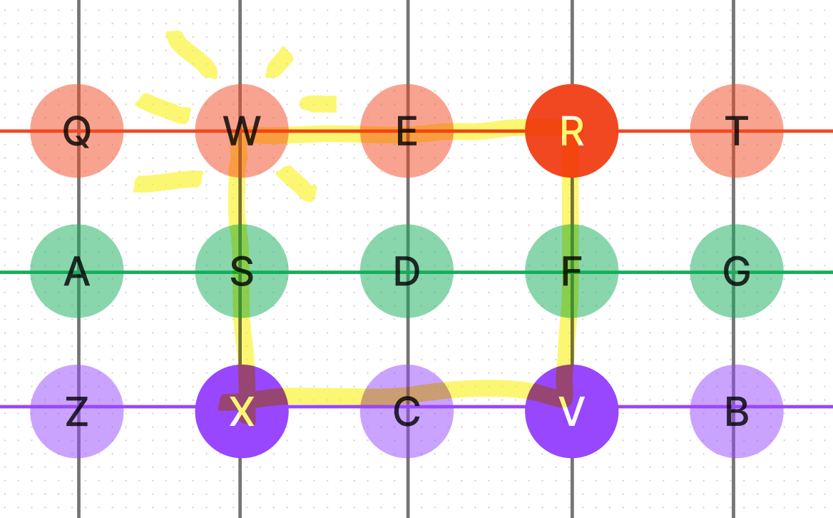
Let’s try one more thing (more coloring ) on the keys:


Ok now it is clear, the “rule of thumb” (pun intended) seems to be:
We want to avoid for two colors to appear together in more than one column (so we don’t have corners)
The simple pattern below ensure this for column of three rows. (14 pins for 21 keys)
")
Simulated Circuit Demos
To help you understand this concept better, I’ve put together two demo simulations on Wokwi that you can run to see the circuit in action:
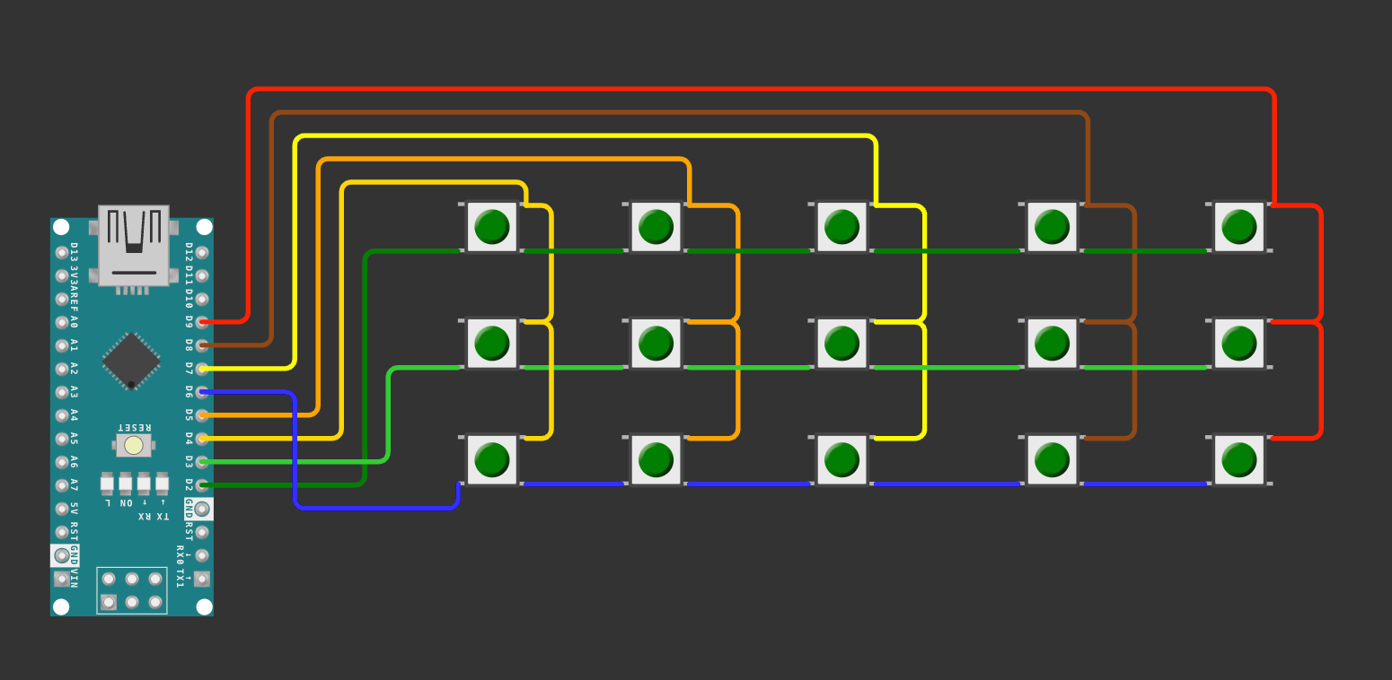
Demo of a matrix with ghosting
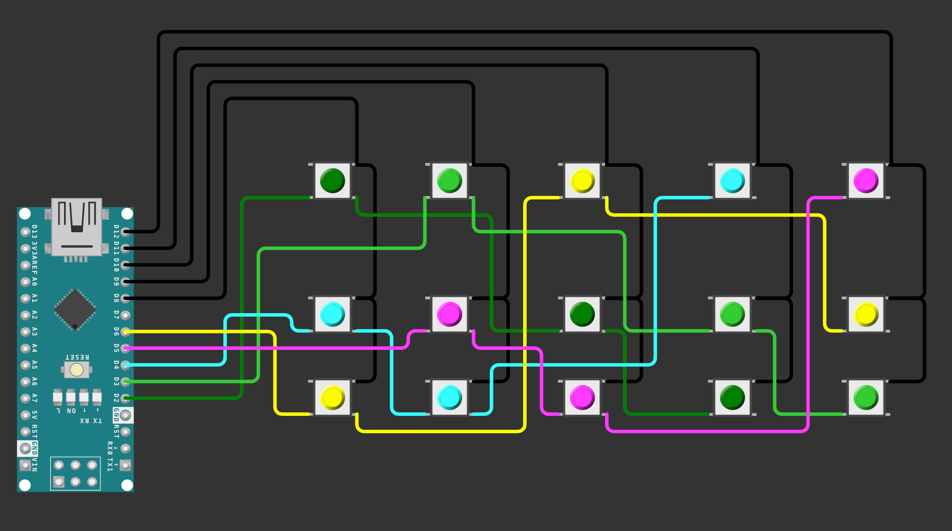
Demo of a matrix with limited ghosting
Conclusion
Its perfect in theory but to accommodate MCUs with limited pins it is acceptable to have some exceptions, the goal being to keep ghosting under control.
I ain't afraid of no ghost!
Moving forward, we’ll continue refining this approach and expand it for a 36 keys.